Assignment 0 Blinky
Due: Monday January 15, 2018 11:59PM
Preface
Welcome to CS140e! We’re really excited that you’ve decided to join us for this inaugural incarnation. We hope you have as much fun taking this class as we’ve had developing it! And, of course, we hope you learn a ton.
We’re hoping to do things a little differently in CS140e than the norm. In particular, we want you to write the majority of the code, and we want your code to execute on real hardware, doing real things. There’s going to be very little scaffolding provided for you, and all of your code will target and run on the Raspberry Pi 3, a quad-core ARMv8 Cortex-A53 based embedded platform.
In CS140e, you’ll be programming in Rust, a “a systems programming language that runs blazingly fast, prevents segfaults, and guarantees thread safety.” You can think of Rust as a successor to C and C++, but it’s more useful to think of it as a brand new language with new concepts. Don’t try to program in Rust as if it’s C, C++, Java, or any other language you’re used to. Instead, see it as an opportunity to learn a new way to write software - a new rusty way. By the end of the term, we think you’ll agree that Rust helps your write more correct, more reliable software - key properties for operating systems!
You’ll be writing a lot of code in CS140e, though we think that the majority of your time will be spent thinking about what needs to happen. We expect that most assignments will take about 10 - 15 hours a week to complete. You should, under no circumstance, procrastinate in CS140e. Start early, ask questions, and have fun - you’ll learn much more if you give yourself a chance to think through hard problems.
We’re here to answer any and all questions. Please don’t hesitate to reach out to us. Best of luck!
Overview
In this assignment, you will set up and test a Raspberry Pi 3, ARM64 development environment for your use throughout the rest of the course. You’ll install the necessary tools and write your first bare-metal application, an LED blinky program, in two languages: C and Rust.
This assignment is divided into 4 phases. In the first phase, you’ll install the
necessary software to communicate with your Pi from your machine. You’ll also
ensure that your Pi works as expected by running a pre-compiled program. In the
second phase, you’ll connect GPIO pin 16 on your Raspberry Pi to an LED on a
breadboard and run a second pre-compiled program to ensure your connections are
sound. In the third phase, you’ll install an aarch64-none-elf cross-compiler,
allowing you to compile and link programs for your Pi from your machine. You’ll
write, compile, and link a C program that toggles GPIO pin 16 on and off,
blinking the LED connected to your Pi. Finally, in phase 4, you’ll install
Rust and the necessary toolchain to write, compile, and link the same program
in Rust.
Phase 0: Getting Started
First, ensure that you are working on this assignment using a compatible machine. For CS140e, compatible means that the machine meets the following requirements:
- Runs a modern Unix natively: Linux, BSD, or macOS
- Runs a 64-bit variant of the OS
- Has a USB-A port or USB-C to USB-A adapter
And has the following software installed: git, wget, tar, screen, and
make.
If you are running Windows, we suggest that you partition your boot disk now and install Ubuntu LTS or Fedora on a secondary partition. You may also have luck working on assignments using the Linux Subsystem for Windows, but we won’t be providing support for or answering questions about this configuration.
Getting your Pi Ready
Check that your Raspberry Pi kit includes all of the following materials:
- 1 Raspberry Pi 3
- 1 1⁄2-sized breadboard
- 1 4GiB microSD card
- 1 microSD card USB adapter
- 1 CP2102 USB TTL adapter w/4 jumper cables
- 10 multicolored LEDs
- 4 100 ohm resistors
- 4 1k ohm resistors
- 10 male-male DuPont jumper cables
- 10 female-male DuPont jumper cables
To set up for this assignment, unbox your Raspberry Pi, micro SD card, breadboard, and USB CP2102 module. Electronics are sensitive to electrostatic discharge, so ensure that you ground yourself by touching something conductive before touching any electronics. Prepare two male to female jumper cables for use as well as one resistor (any resistor!) and one LED. Finally, ready the USB microSD card adapter.
Getting the Skeleton Code
Clone the assignment 0 skeleton git repository to your development machine and
then fetch the required files by running make fetch inside the directory:
git clone https://cs140e.sergio.bz/assignments/0-blinky/skeleton.git 0-blinky
cd assignment0
make fetch
Feel free to explore the contents of the repository.
Phase 1: Baking Pi
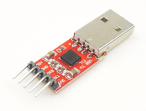
The primary means through which you’ll be powering and communicating with your Pi is via a CP2102 USB module. That’s the red USB dongle with the five pins.
Installing Drivers
If you’re running Linux, you don’t have to do anything for your machine to
recognize the module correctly. If you’re running macOS, you’ll need to install
a driver. Download this zip
file,
double-click to unzip it, and then double-click the resulting
SiLabsUSBDriverDisk.dmg file. Accept the terms. In the newly mounted volume,
you’ll see a Silicon Labs VPC Driver.pkg file. Double-click to run and follow
the on-screen prompts to install the driver. Once complete, restart your
machine. After rebooting, you’ll be ready to continue.
Insert the CP2102 module into a USB slot on your machine. If everything worked
well, you should see a new file in /dev corresponding to the device. On macOS,
this will be /dev/tty.SLAB_USBtoUART. On Linux, this will likely be
/dev/ttyUSB0. Before continuing, you may wish to record this path. You’ll be
referring to it a lot in the future.
Now unplug the CP2102 module from your machine.
Powering the Pi
We’ll now connect the Raspberry Pi to the CP2102 module using the four female-female jumper cables included in the module’s package. The table below shows which pins on the CP2102 module you should connect to which pins on the Raspberry Pi:
| CP2102 Pin | Pi Physical Pin |
|---|---|
| +5v | 4 |
| GND | 6 |
| RXD | 8 |
| TXD | 10 |
Here’s how the pins are numbered on the Raspberry Pi 3:

Here’s what the connections should look like:
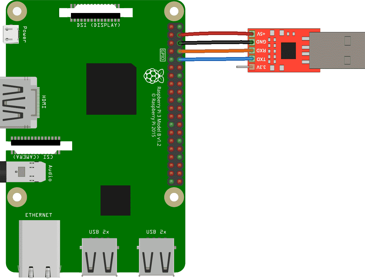
Double-check, triple-check, and quadruple-check your connections! Then, get a friend to double-check your connections! Incorrect wiring can result in a fried Raspberry Pi, which will result in an automatic F in this course. Okay, that last bit isn’t true, but Raspberry Pi 3’s are expensive, and we don’t want to pass out additional ones if we can prevent it. So, quintuple-check your connections before continuing!
If you’re confident in your connections, it’s time to plug in your CP2102 module into your computer. If all went well, you should see a red LED light on your Raspberry Pi shining bright. Congratulations! You’re now able to power and communicate with your Pi.
Running Programs
As discussed in lecture, the Raspberry Pi loads programs on boot from the on-board microSD card. We’ll now set up our microSD card with a custom program for the Raspberry Pi to load.
Take the microSD card and insert it into the USB microSD card adapter. Then,
plug the adapter into your machine. You should see a new volume mounted on your
machine. Copy the three files inside of the files/firmware directory in the
skeleton (bootcode.bin, config.txt, and start.elf) to the root of the
microSD card. (If you don’t see these files, make sure you’ve run make fetch
inside the skeleton repository.) As discussed in lecture, these are three of the
four files read by the GPU on boot. The fourth, kernel8.img, is the boot
program, which we are about to install.
What are bootcode.bin, config.txt, and start.elf?
These specially-named files are recognized by the Raspberry Pi’s GPU on
boot-up and used to configure and boostrap the system. bootcode.bin is the
GPU’s first-stage bootloader. Its primary job is to load start.elf, the
GPU’s second-stage bootloader. start.elf initializes the ARM CPU,
configuring it as indicated in config.txt, loads kernel8.img into memory,
and instructs the CPU to start executing the newly loaded code from
kernel8.img.
Now, copy files/activity-led-blink.bin from the skeleton to the root of the
microSD card and name the file kernel8.img. Unmount the microSD card,
disconnect the USB adapter from your machine, and remove the microSD card from
the USB adapter. Ensure your Raspberry Pi 3 isn’t currently powered. Then,
insert the microSD card into the Rasperry Pi 3. Plug in the Pi. In just a short
moment, you should see a green LED on the Raspberry Pi board blinking once every
two seconds for one second at a time. You should also see a blue LED on the USB
CP2102 adapter blinking at the same frequency. This indicates that data is being
sent to/from the Raspberry Pi.
But what data? To see the data the Raspberry Pi is sending, you’ll need to run a
serial console emulator that connects to the CP2102 module and reads the
incoming data. We’ll use screen since it comes preinstalled on Linux and
macOS. Recalling the /dev path from before, connect to the CP2102 USB module
with screen by running:
screen /dev/<your-path> 115200On Linux, you may have to use sudo to run the command. Alternatively, you can
add yourself to the dialout user group to avoid using sudo: sudo gpasswd
--add <your-username> dialout.
You should see friendly messages from your Raspberry Pi. To exit screen, use
<ctrl-a> k then answer y at the prompt.
Phase 2: LED There Be Light
In this phase, you’ll connect GPIO pin 16 (physical pin 36) on the Raspberry Pi to an LED light on a breadboard. You’ll test the LED using a pre-compiled binary. Before starting, ensure your Raspberry Pi is unplugged.
Is it safe to simply unplug the USB TTL adapter?
Yes! On a traditional computer, and later on in the course, removing the power source without consideration is a bad idea because operations, typically on the disk, may be in-flight. Stopping these operations midway can result in damaged hardware or inconsistent state on the next boot-up. For now, our Pis have no state or moving hardware, so we don’t need to worry about this. Feel free to simply unplug its power source!
GPIO: General Purpose I/O
GPIO stands for General Purpose Input/Output. As the name implies, GPIO is a general mechanism for transmitting data/signals into and out of some device through electrical pins, known as GPIO pins.
A GPIO pin can act as either an output or input. When a GPIO pin is acting as an output, it can either be set on or off. When on, the Raspberry Pi drives the pin at 3.3v. When the GPIO pin is off, no current flows through the pin. When a GPIO pin is acting as an input, the Raspberry Pi reports whether the pin is being driven at 3.3v or not.
GPIO pins are incredibly versatile and can be used to implement a wide array of functionality. You can read more about GPIO on the Raspberry Pi Foundation’s GPIO Usage Documentation.
Testing the LED
We’ll start by constructing the circuit below:

If you’ve never used a breadboard, we suggest reading through SparkFun’s “How to Use a Breadboard” guide. This circuit connects an LED to always-on 3.3v power on the Raspberry Pi. Note that pin 1 (+3.3v) on the Raspberry Pi should go to the longer leg of your LED. The shorter leg is connected to the resistor which in-turn is connected to pin 14 (ground) on the Pi.
After you’ve confirmed your connections, plug the Raspberry Pi in. Your LED should turn on. After you’ve confirmed that the LED works as expected, unplug your Rapsberry Pi. Then, move the jumper cable from pin 1 on the Pi to pin 36 (GPIO Pin 16) as illustrated below:

Copy files/gpio16-blink.bin from the skeleton repository to the microSD card
as kernel8.img, replacing any existing kernel8.img file on the card. Start
the Raspberry Pi with the new image. Your LED should start blinking.
Phase 3: Shining C
In this phase, you’ll write the program that produced gpio16-blink.bin in C.
You’ll write your code in phase3/blinky.c. To be able to compile C and assembly
programs for the Raspberry Pi, we’ll install a cross compiler for the
aarch64-none-elf target.
Installing a Cross-Compiler
We’ll now install the aarch64-none-elf GNU toolchain (gcc and friends),
allowing you to compile and link C and assembly code for our Raspberry Pi from a
non-Raspberry Pi machine.
macOS Installation Steps
First, we’ll install homebrew, a popular package manager for macOS. If you already have
brewinstalled, skip this step.Install the Xcode command line tools by running the shell command below. A dialog should pop up on your screen. Click “Install” when it appears.
xcode-select --installRun Homebrew’s install script by using the command below. The script will guide you through the rest of the install process.
/usr/bin/ruby -e "$(curl -fsSL https://raw.githubusercontent.com/Homebrew/install/master/install)"
We’ll now install the
aarch64-none-elftoolchain using homebrew.“Tap” into a custom set of macOS cross-compilation packages and install the toolchain using the command below.
brew tap SergioBenitez/osxct
brew install aarch64-none-elf
Ensure it works by running the following command and checking that its output is identical to what is displayed below:
$ aarch64-none-elf-gcc --version
aarch64-none-elf-gcc (GCC) 7.2.0
Copyright (C) 2017 Free Software Foundation, Inc.
This is free software; see the source for copying conditions.  There is NO
warranty; not even for MERCHANTABILITY or FITNESS FOR A PARTICULAR PURPOSE.
Linux Installation Steps
Download and unarchive aarch64-none-elf-linux-x64.tar.gz, then move the resulting
arch64-none-elfdirectory to/usr/local/bin:wget https://cs140e.sergio.bz/files/aarch64-none-elf-linux-x64.tar.gz tar -xzvf aarch64-none-elf-linux-x64.tar.gz sudo mv aarch64-none-elf /usr/local/binAdd
/usr/local/bin/aarch64-none-elf/binto your$PATH. The exact means to do this depends on your Linux distribution. For most, adding the following to~/.profileshould suffice:PATH="/usr/local/bin/aarch64-none-elf/bin:$PATH"Ensure it works by running the following command and ensuring you get a GCC version number as output:
aarch64-none-elf-gcc --version
Talking to Hardware
The vast majority of modern hardware devices communicate with software through memory-mapped I/O. The concept is simple: devices expose their functionality through the machine’s memory and provide a specification about what will happen if certain addresses are read or written to. Addresses are usually separated into 32 or 64-bit sized regions known as registers. Registers are usually named to indicate their functionality. Registers can be read-only, write-only, or read/write.
How do we know which registers a device exposes, where in memory they’re mapped, and what they do? Device manufacturers document all of this information in what is typically referred to as a “data sheet”, “device manual”, or simply “documentation”. There is no widespread format for how devices are documented, and documentation quality is hit or miss. Reading and understanding hardware documentation is a skill and art.
GPIO Memory-Mapped Interface
The documentation for many of the peripherals on-board the Rasperry Pi can be found in Broadcom’s BCM2837 ARM Peripherals Manual. The documentation for GPIO, for example, is on page 89.
Wait, aren’t we using a BCM2837 chip?
If you open the manual we’ve linked you to, you’ll see references to the BCM2835 chip everywhere. This is because we’ve simply taken the documentation for the BCM2835 chip, fixed relevant errata, and fixed the title to say BCM2837.
The BCM2837 and BCM2835 share the same peripherals with the same relative
memory-mapped interfaces. The main difference is that the chips differ in
their physical memory configuration. This results in the BCM2837 having a
peripheral physical base address of 0x3F000000 as opposed to the BCM2835’s
0x20000000. But both chips map this range to the peripheral base address
of 0x7E000000. In short, a peripheral address 0x7EXXXXXX is at physical
address 0x3FXXXXXX on the BCM2837. The “BCM2837” documentation we’ve linked
to contains this change.
For this assignment, we’ll only need to use the following three registers:
| name | peripheral address | description | size | read/write |
|---|---|---|---|---|
| GPFSEL1 | 0x7E200004 | GPIO Function Select 1 | 32 bits | R/W |
| GPSET0 | 0x7E20001C | GPIO Pin Output Set 0 | 32 bits | W |
| GPCLR0 | 0x7E200028 | GPIO Pin Output Clear 0 | 32 bits | W |
We’ve copied this information directly from page 90 of the documentation.
Now, read the documentation for GPFSELn register on pages 91 and 92. We write
to this register to set up a pin as an output or input. Which value to which
field in register GPFSEL1 must be written so that GPIO pin 16 is set as an
output?
Now, read the documentation for the GPSET0 and GPCLR0 registers on page 95.
We write to GPSET0 to set a pin (turn it on) and write to GPCLR0 to
clear a pin (turn it off). Which value do we write to which field in these
registers to set/clear pin 16?
Writing the Code
The phase3/ directory in the assignment skeleton contains a scaffold for
building a binary suitable for running on the Raspberry Pi 3. We won’t explain
crt0.S, layout.ld, or Makefile for now. Instead, you’ll work on
blinky.c.
In blinky.c, you’ll find that we’ve declared the physical addresses of the
three relevant registers at the top of the file. Your task is to complete the
main() function so that GPIO pin 16 is set-up as an output and then
continuously set and cleared to blink the LED. We’ve also provided rudimentary
“sleep” functions that stall the CPU for roughly the amount of time the function
name indicates. You can use these to pause between sets and clears.
When you are ready to test your program, compile it by running make in your
shell. If all goes well, this will create the file blinky.bin which you can
rename kernel8.img and copy to your microSD card to run on your Raspberry Pi.
When you have a working kernel8.img, proceed to phase 4.
Hint: Pin function selection, setting, and clearing can each be implemented in one line of code.
Hint: Recall the <<, |, &, and ~ bitwise operators in C.
Hint: Recall that binary/hex numbers in C are written as 0b011 and 0x03, respectively.
Phase 4: Rusting Away
In this phase, you’ll write the program that produced gpio16-blink.bin in
Rust. You’ll write your code in phase4/src/lib.rs.
Installing Rust and Xargo
To compile Rust programs, we first need to install the Rust compiler. We’ll also
install xargo, a wrapper around Rust’s package manager cargo that lets us
easily compile for targets like the Raspberry Pi.
Go to https://rustup.rs and follow the instructions to install
rustup. Ensure that Rust was installed successfully by runningrustc --version.We’ll now use
rustupandcargoto switch to a nightly release of Rust, install the source code for Rust’s standard libraries onto our machine, and installxargo:rustup default nightly-2018-01-09 rustup component add rust-src cargo install xargoTest the installed commands and ensure your versions match:
$ rustc --version
rustc 1.25.0-nightly (b5392f545 2018-01-08)
$ xargo --version
xargo 0.3.10
cargo 0.25.0-nightly (a88fbace4 2017-12-29)
That’s it! You now have a working Rust compiler running on your system.
Writing the Code
To write the required code in phase4/src/lib.rs, you’ll only need to know the
following Rust:
You can read and write from a raw pointer (
*mut T) using theread_volatile()andwrite_volatile()methods.For example, if we have the following declarations:
const A: *mut u32 = 0x12 as *mut u32;
const B: *mut u32 = 0x34 as *mut u32;
We can write the 32-bit unsigned integer at address
0x12to0x34with the following:B.write_volatile(A.read_volatile());Local variables can be declared with
let variable_name = expression;.Using the
Adeclaration from the previous example, we can read the value at address0x12to a local variablevalueas follows:let value = A.read_volatile()You can call a function
fn f(param: usize);withf(123);.A
loopblock can be used to repeat a block infinitely:loop { do_this_again_and_again(); }Rust defines the following bitwise operators:
!- unary bitwise inversion<<- left shift binary operator>>- right shift binary operator|- bitwise OR binary operator&- bitwise AND binary operator
You are now ready to implement the blink program in phase4/src/lib.rs.
Translate your C implementation into Rust in the kmain function. You’ll find
that we’ve declared the physical addresses of the three relevant registers at
the top of the file. We’ve also provided a rudimentary “sleep” function that
stalls the CPU for roughly the amount of time the function name indicates. You
can use the function to pause between sets and clears.
When you are ready to test your program, compile it by running make from the
phase4 directory in your shell. If all goes well, this will create the file
build/blinky.bin which you can rename kernel8.img and copy to your microSD
card to run on your Raspberry Pi. When you have a working kernel8.img, you
have completed assignment 0! Proceed to the next phase for submission
instructions.
Hint: Your Rust and C code should look very similar.
Submission
Once you’ve completed the tasks above, you’re done and ready to submit! Ensure
you’ve commited your changes. Any uncommited changes will not be submitted
with your assignment. When you’re ready, run make submission from the
assignment0 directory and then proceed to the submission page to upload your
submission.